Common Circuits for Robotics
One of the joys of being a roboticist is getting to tinker with hardware. In this post I want to note down common circuits I have used in the past, along with methods to specify the parts (mainly resistor values). All circuit diagrams are made with Fritzing.
Switch
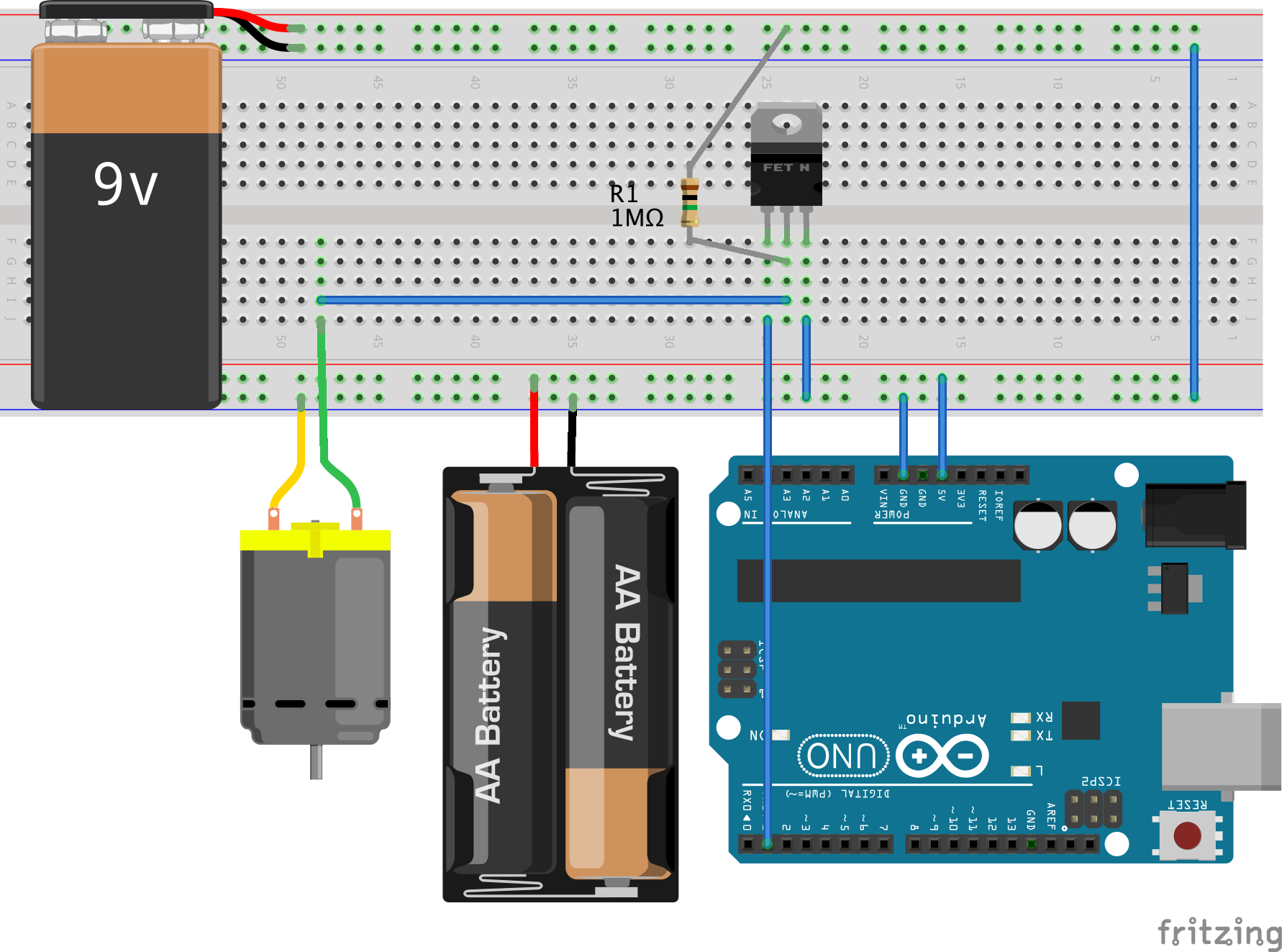
Pretty straightforward use of an N-channel MOSFET.
Note the 1 M$\Omega$ pull-up resistor at the drain terminal of the MOSFET. In the
following circuit diagram, MOSFET terminals are gate - drain - source from left
to right.
Reading an NPN Sensor
Many analog sensors are NPN sensors e.g. pressure sensors. These sensors have an NPN transistor inside. The quantity being sensed (e.g. pressure) drives the base, which controls the current flowing from collector to emitter. The emitter is connected to the ground. By biasing the collector properly, you can get a voltage in the 1 V - 5 V range, which can be read with an Arduino analog input pin. See the circuit below.
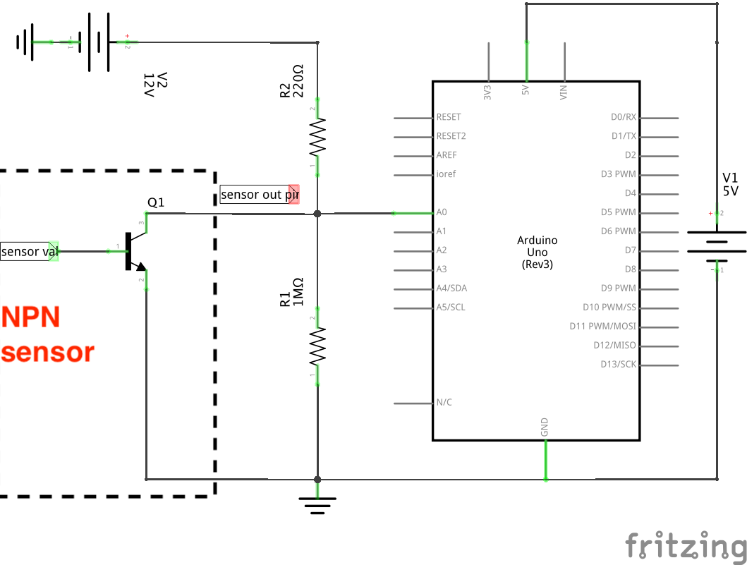
We will need two values from the NPN sensor datasheet:
- Output voltage range $V_{min}$ - $V_{max}$, here 1 V to 5 V. This corresponds to the “active region” of the NPN transistor, where the base is able to linearly modulate the collector-emitter current.
- Output impedance $R_{NPN}$. Let us assume it is 1 K$\Omega$ for this sensor.
Picking $R_1$
Because it is in parallel with the transistor, we know $R_1$ will have a 1 V - 5 V drop across it. We can pick a value that will result in a safe power dissipation. 1 M$\Omega$ is good, because the resultant $\frac{V^2}{R}$ power dissipation will then be 1 $\mu$W - 25 $\mu$W. Most hobby resistors are safe up to 0.25 W.
Picking $R_2$
This is more interesting. Let’s say it is connected to a 12 V power supply at the other end. The important consideration here is also safe power dissipation. Current through $R_2$, $I_2 = I_1 + I_{NPN}$. Looking at the maximum values of these currents for maximum power dissipation,
\[\begin{align*} P_2 &= I_2^2 R_2\\ &= (I_1 + I_{NPN})^2 R_2\\ &= V_{max}^2 \left( \frac{1}{R_{NPN}} + \frac{1}{R_1} \right)^2 R_2\\ &= 25 \left( 10^{-3} + \frac{1}{R_1} \right)^2 R_2 \end{align*}\]If $R_2$ is rated at 0.25 W,
\[\begin{align*} P_2 &\lt 25\times 10^{-2}\\ \implies \left( 10^{-3} + \frac{1}{R_1} \right)^2 R_2 &\lt \frac{10^{-2}}{5}\\ \implies R_2 &\lt \frac{R_1^2}{500 \left( R_1\times 10^{-3} + 1 \right)} \end{align*}\]I have intentionally kept $R_1$ in the above analysis because:
- Eventhough we chose 1 M$\Omega$ as its value, in practice the value of hobby resistors is not very accurate. So you can measure it with a multimeter and then calculate $R_2$ accordingly.
- It shows that any value of $R_2$ less than that limit will work. You do not need a specific value resistor for $R_2$. So I prefer to use a rotary potentiometer for $R_2$.
4-20 mA Current Loop Controller
Many actuators are controlled by a 4-20 mA control loop. The idea is that the actuator is part of a current loop, and will actuate proportional to the value of current in that loop. This value should be between 4 mA and 20 mA. Arduino has PWM output pins, so the problem is designing a circuit that converts the PWM voltage signal to a proportional current value. We will do this with an op-amp.
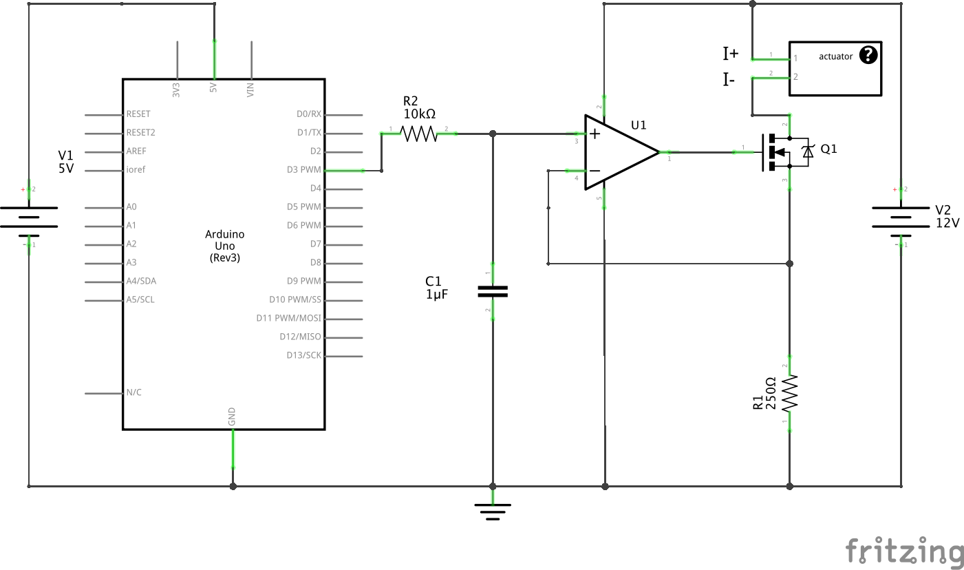
- First, the PWM signal is converted to a smooth analog signal using a lowpass RC filter ($R_2$ and $C_1$). You can use this PWM calculator to pick $R$ and $C$ values.
- Using the “golden rules” of op-amps we know that the voltage drop across $R_1$ will equal the $RC$ filter output. $R_1$ does the job of converting voltage to current.
- The 12 V battery - actuator - MOSFET Q1 - $R_1$ are all in series and form the current loop. Current $I = \frac{V}{R_1}$. If $V$ is varied from 1 V to 5 V using the Arduino PWM, the current $I$ varies from 4 mA to 20 mA, because $R_1$ is 250 $\Omega$.
- $R_1$ needs to be precisely 250 $\Omega$, so make sure you buy a precision resistor!
Links and Sources
The following sources have been helpful to me: